
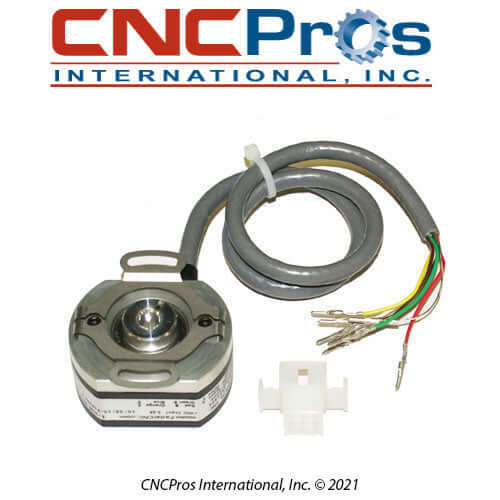
ENC-0004 FADAL SPINDLE ENCODER. ACCUCODER
ENC-0004 FADAL SPINDLE ENCODER. ACCUCODER
Couldn't load pickup availability
Share
ENC-0004 FADAL SPINDLE ENCODER. ACCUCODER
ENC-0004 FADAL SPINDLE ENCODER. ACCUCODER
WHY IS THE ENC-0004 SUPERIOR AND HOW DOES IT WORK?
Technical Overview: The Fadal 1000-Line Accu-Coder (ENC-0004)
Think of your Fadal vector drive as a high-precision amplifier, and the ENC-0004 1000-Line Accu-Coder as its eyes. In vector-mode operations, this encoder provides the real-time feedback required for the drive to calculate flux and torque vectors. Without a clean, high-resolution signal from this unit, the drive loses its frame of reference, leading to erratic current draw, "pegged" load meters, and catastrophic drive faults.
At CNCPros International, we have spent nearly three decades diagnosing Fadal spindle performance. We know that the ENC-0004 is frequently misdiagnosed as a "bad drive" when, in fact, the issue is signal noise or pulse degradation.
Technical Operation: Pulse Integrity
The ENC-0004 is a differential line-driver encoder, providing high-speed quadrature signals (A/A- and B/B-) that allow the drive to interpret both velocity and rotational direction.
- Pulse Resolution: The 1000-line resolution provides the high-fidelity feedback necessary for Fadal’s orientation (M19) and rigid tapping cycles.
- Differential Signaling: By using complementary signals (A+/A-), the encoder effectively cancels out electromagnetic interference (EMI) along the cable run, ensuring the signal arriving at the drive is as clean as the signal leaving the motor.
Field Diagnostic Authority
Before replacing your Baldor or Glentek drive, use our field-proven diagnostic hierarchy to isolate the encoder.
1. The Oscilloscope Method (Gold Standard)
Use a dual-channel oscilloscope to view the A and B channels simultaneously. Look for:
- Jitter/Noise: Any "fuzz" on the square wave transitions indicates cable shielding failure or encoder bearing wear.
- Missing Pulses: A single missing pulse will confuse the drive's vector calculation, leading to an immediate over-current trip.
2. The Fluke Meter "Quick-Check"
- AC Voltage Test: Set your meter to AC. Rotate the spindle at orientation speed. You should read approximately 2.8 VAC between the Supply Common and any signal line (A+, A-, B+, B-).
- DC State Logic: Set your meter to DC. Monitor the channel voltages relative to Ground. You should see a clean toggle between 0 VDC and 3.5 VDC.
Crucial Logic: A+ and A- must always be in opposing states (If A+ is 3.5V, A- must be 0V). If A+ and A- are the same, the encoder is internally faulted.
Wire Pinout and Connectivity
To ensure signal integrity, verify your connections against this standard pinout. Mismatched wiring or high-resistance terminals are the primary cause of intermittent spindle speed instability.
| Signal Pin | Function |
| A+ | Channel A Positive |
| A- | Channel A Complement |
| B+ | Channel B Positive |
| B- | Channel B Complement |
| +5V | Power Supply |
| GND | Supply Common / Shield |
The CNCPros International Advantage
At CNCPros International, we don’t just move parts—we move production lines.
- OEM Authenticity: The ENC-0004 is a factory-spec Accu-Coder. We refuse to sell generic substitutes, as the timing tolerances and signal output levels are calibrated specifically for Fadal’s drive handshake.
- Expert Integration: Our team can walk you through the signal-tracing process on your specific Baldor drive, ensuring you don't replace a functional drive when a simple encoder swap or cable repair will restore your machine's performance.
- Reliability Guarantee: Every unit comes with our industry-backed 90-day warranty, ensuring that your spindle’s feedback loop is restored to factory-new standards.
Is your spindle load meter pulsating or your RPM wandering?
Don't let a "Ghost" drive fault bleed your budget. Reach out to our Order Desk at 1-208-888-9236. Let our specialists help you verify your signal timing and determine if the ENC-0004 is the final missing piece of your spindle's stability
Troubleshooting
How to Check Your Fadal VMC Spindle Encoder
Here is a simple, step-by-step guide to checking if your Fadal VMC encoder is working correctly.
A key sign that an encoder is starting to fail is when you see the spindle RPM surge up and down and the load meter spike. This happens because the encoder is sending a bad signal to the machine control.
The best way to test the encoder is with a tool called an oscilloscope, which lets you see the electrical signals. A simple voltmeter can't show you all the details you need to know.
What the Encoder Does
The encoder sends three signals to the Fadal control:
- Channels A and B: These two signals tell the control how fast and in what direction the spindle is spinning.
- Index Pulse (Z Channel): This is a single signal that tells the control when the spindle has completed one full turn.
The Best Way to Test (Using an Oscilloscope)
- Turn off the machine. Unplug the encoder's cable.
- Connect the oscilloscope to the wires for Channels A and B.
- Slowly turn the spindle by hand.
- Look at the screen. You should see two clean, even square waves that look a little out of sync with each other. The voltage should be a steady 0V to 5V.
If you see no signal, the encoder is likely broken or has no power.
If the signals are messy or jumpy, the encoder is probably misaligned or damaged.
If the signals aren't properly "out of sync," the machine will get confused about the direction of rotation.
A Basic Test (Using a Voltmeter)
This method can tell you if the encoder is completely dead, but not if it has a smaller problem.
- Turn off the machine.
- Connect your voltmeter to the encoder's power wires to make sure it's getting 5V.
- Connect the voltmeter to the signal wires for Channels A and B.
- Slowly turn the spindle by hand. You should see the voltage go up and down. If you see no change, the encoder is likely broken.
Using the Fadal Machine's Own Tools
You can also use the Fadal control to help diagnose a problem:
- Check for alarms. Look for any alarms related to the spindle's speed or position.
- Try Spindle Orientation. In the MDI screen, run the command M19. If the spindle doesn't lock into position consistently, the encoder is probably the problem.
- Swap it out. If you have another encoder on a different axis that is the same part, you can temporarily swap them. If the problem moves with the encoder, you've found the issue.